
Transformer rewinding is a specialized repair process that restores the electrical and mechanical integrity of a transformer by replacing damaged windings while preserving the serviceable components of the unit. When performed correctly, transformer rewinding can extend the transformer service life by many years or even decades, depending on the condition of the core, operating environment, and maintenance practices, reduce replacement costs, and restore electrical performance to the original specifications or approved engineering requirements. The transformer rewinding process requires careful engineering, precise manufacturing techniques, comprehensive electrical testing, and strict adherence to insulation and safety standards.
Whether used in industrial plants, utility substations, renewable energy systems, marine equipment, or aerospace applications, transformer rewinding has become a practical alternative to replacing high-value transformers. However, successful rewinding depends on understanding the original transformer design, accurately diagnosing the failure, and rebuilding the windings without compromising magnetic performance, insulation coordination, or thermal characteristics.
What Is Transformer Rewinding?
Transformer rewinding is the engineering process of removing damaged or deteriorated primary and secondary windings from a transformer and manufacturing new windings that match the original electrical, mechanical, and thermal design. The rebuilt transformer is then reassembled, insulated, dried, impregnated, and thoroughly tested to verify that it meets its original operating specifications.
Unlike minor transformer repairs, transformer rewinding involves reconstructing the transformer’s electromagnetic circuit while preserving reusable components such as the magnetic core, tank, enclosure, cooling system, and structural hardware whenever they remain within acceptable engineering tolerances.
Understanding how a transformer operates helps explain why winding integrity is so critical. During normal operation, electrical energy is transferred between windings through What Is a Transformer and the principle of Electromagnetic Induction, where changing magnetic fields induce voltage without direct electrical contact between circuits.
Because the windings carry the operating current and generate the magnetic field responsible for power transfer, they are typically the components most vulnerable to electrical faults, thermal aging, insulation breakdown, and mechanical stresses.
Why Transformer Windings Fail?
Transformer windings are subjected to continuous electrical, thermal, mechanical, and environmental stresses throughout their service life. Although transformers are designed for decades of reliable operation, prolonged exposure to these stresses gradually weakens insulation systems and conductor integrity.
Failure rarely results from a single event. Instead, most winding failures develop through a combination of aging, excessive loading, abnormal operating conditions, or external electrical disturbances that progressively degrade insulation until dielectric failure occurs.
When winding damage becomes extensive, transformer rewinding often provides the most economical solution while maintaining the transformer’s original magnetic design.
Thermal Aging
Heat is the primary factor affecting transformer insulation life. Every transformer is designed to operate within a specified temperature rise, but excessive operating temperatures accelerate insulation deterioration.
Common causes include:
- Continuous overload operation
- Poor cooling performance
- Blocked ventilation
- Elevated ambient temperatures
- Inadequate maintenance
As insulation ages, its dielectric strength decreases, making it increasingly susceptible to electrical breakdown between adjacent turns or winding layers.
Electrical Faults
High-energy electrical events place enormous stress on transformer insulation systems.
These include:
- Short circuits
- Switching transients
- Lightning surges
- Internal arcing
- Overvoltage conditions
Repeated electrical stress weakens insulation materials until partial discharge develops, eventually leading to complete winding failure.
Proper insulation coordination is particularly important in High Voltage Transformer applications, where dielectric clearances, insulation grading, and impulse withstand capability become increasingly critical.
Mechanical Forces
Short-circuit currents generate extremely large electromagnetic forces within transformer windings.
These forces can cause:
- Conductor displacement
- Winding deformation
- Turn-to-turn contact
- Compression of insulation
- Loosened winding supports
Even if the transformer continues operating after a fault, hidden mechanical damage may eventually result in insulation failure months or years later.
The magnitude of these forces depends on conductor geometry, support structures, and the distribution of Magnetic Flux throughout the transformer core.
Moisture and Environmental Contamination
Moisture significantly reduces the dielectric strength of transformer insulation.
Water contamination may result from:
- Aging seals
- Condensation
- Oil contamination
- Flood exposure
- Improper storage
Dust, chemicals, salt, and industrial contaminants further accelerate insulation degradation by creating conductive paths and reducing surface insulation resistance.
Transformers operating in harsh industrial environments require periodic inspection to identify contamination before irreversible damage occurs.
How Transformer Windings Work

To understand transformer rewinding, it is important to understand the function of the windings themselves.
Transformer windings are insulated copper or aluminum conductors carefully arranged around the magnetic core. Their geometry determines voltage ratio, current capacity, impedance, efficiency, and thermal performance.
When alternating current flows through the primary winding, it creates a changing magnetic field inside the transformer core. This alternating magnetic field induces a voltage in the secondary winding according to the principles of electromagnetic induction.
The efficiency of this energy transfer depends heavily on the magnetic properties of the core, including its Flux Density, operating limits, and resistance to Magnetic Saturation.
Different transformer designs use different winding arrangements depending on voltage level, application, cooling requirements, and installation constraints.
For example:
- Single phase transformer designs commonly serve residential, commercial, and control applications.
- 3 phase transformer configurations provide efficient power distribution for industrial equipment and utility networks.
- Distribution transformer windings are optimized for continuous operation and high efficiency across varying load conditions.
The winding design also varies depending on insulation class, conductor size, cooling method, and operating frequency.
Components Evaluated Before Rewinding
A professional transformer rewinding project begins long before any conductor is removed.. Engineers first determine whether rewinding is technically feasible and economically justified.
Several critical components are carefully inspected to ensure they remain suitable for continued service.
Magnetic Core
The magnetic core is usually the most valuable component retained during transformer rewinding.
It is inspected for:
- Lamination damage
- Core displacement
- Mechanical distortion
- Corrosion
- Localized overheating
- Increased core losses
If significant deterioration is present, rebuilding the windings alone may not restore the transformer’s original efficiency.
The performance of the rebuilt transformer depends greatly on the condition of the Transformer Core Materials, since damaged laminations increase eddy current losses, operating temperature, and noise.
Insulation System
Although the windings are replaced, many structural insulation components require detailed inspection.
Engineers evaluate:
- Pressboard spacers
- Cylinders
- End rings
- Barriers
- Wedges
- Insulating supports
Any compromised insulation is replaced to ensure long-term dielectric reliability.
Modern insulation materials often provide improved thermal endurance compared to older systems, allowing the rewound transformer to achieve equal or better reliability than the original design when engineered correctly.
Tank and Cooling System
The transformer enclosure is inspected for structural integrity and cooling performance.
Typical inspections include:
- Tank corrosion
- Oil leaks
- Radiator condition
- Cooling fans
- Pumps
- Bushings
- Conservator system
- Pressure relief devices
Restoring these components during transformer rewinding helps ensure that the rebuilt transformer operates within its intended temperature limits, maximizing insulation life.
When Is Transformer Rewinding Recommended?
Transformer rewinding is not appropriate for every failed transformer. Engineers evaluate the condition of the entire unit before deciding whether repair or replacement offers the best long-term value.
Rewinding is commonly recommended when:
- The magnetic core remains mechanically and electrically sound.
- The transformer has experienced winding insulation failure without catastrophic structural damage.
- Replacement lead times are long.
- The transformer is custom-designed or difficult to replace.
- The cost of transformer rewinding is substantially lower than manufacturing a new transformer.
- Original performance specifications can be restored through proper engineering and manufacturing.
This is especially true for specialized units developed through Custom Transformer Design, where unique electrical characteristics, mechanical dimensions, or application-specific requirements make direct replacement expensive or impractical.
For many industrial facilities, restoring an existing transformer through professional rewinding minimizes downtime while preserving compatibility with the existing electrical infrastructure.
The Complete Transformer Rewinding Process

Transformer rewinding is a controlled engineering process that restores the transformer to its original electrical and mechanical performance. Every stage must be carefully documented because even small deviations in conductor dimensions, insulation thickness, winding arrangement, or assembly sequence can alter voltage ratio, impedance, efficiency, or thermal performance.
Professional transformer rewinding facilities follow established manufacturing procedures and quality control systems to ensure the rebuilt transformer performs as intended. While individual processes may vary depending on transformer type and application, the overall workflow follows a consistent sequence.
1. Initial Inspection and Failure Analysis
Before any disassembly begins, engineers perform a comprehensive inspection to determine the root cause of the failure rather than simply repairing the visible damage.
The transformer is visually examined for signs of overheating, insulation deterioration, oil leakage, mechanical distortion, contamination, or evidence of electrical faults. Historical operating data, maintenance records, and fault reports are also reviewed whenever available to identify conditions that contributed to the failure.
Accurate failure analysis is essential because transformer rewinding without correcting the underlying problem may result in premature failure after the transformer is returned to service.
2. Electrical Diagnostic Testing
A complete series of electrical tests is performed to evaluate the condition of the transformer before dismantling. These measurements provide valuable information about the extent of damage and establish a reference for post-repair verification.
Typical diagnostic testing includes:
- Insulation resistance testing
- Winding resistance measurement
- Turns ratio testing
- Excitation current testing
- Short-circuit impedance measurement
- Dielectric withstand testing
- Polarization Index (PI)
- Oil quality analysis for oil-filled transformers
For larger power transformers, additional diagnostic methods such as dissolved gas analysis (DGA), frequency response analysis (FRA), and partial discharge testing may also be performed to identify hidden insulation or mechanical defects.
3. Transformer Disassembly
Once testing is complete, the transformer is carefully dismantled.
Each component is documented and labeled before removal to preserve the original mechanical arrangement.
Disassembly generally includes:
- Removing the tank cover
- Draining insulating oil (if applicable)
- Disconnecting leads
- Removing bushings
- Extracting the core-and-coil assembly
- Separating structural insulation components
Photographs, dimensional measurements, and winding documentation are collected throughout the process to ensure accurate reconstruction.
4. Removal of Damaged Windings
The failed windings are removed without damaging the magnetic core or reusable insulation structures.
During removal, engineers carefully record:
- Number of turns
- Conductor dimensions
- Winding direction
- Layer arrangement
- Tap positions
- Insulation thickness
- Connection locations
- Lead routing
This information forms the foundation for manufacturing transformer replacement windings that reproduce the original electrical characteristics.
If original design documentation is unavailable, reverse engineering techniques are used to reconstruct the winding design from physical measurements and electrical analysis.
5. Core Inspection and Refurbishment
With the windings removed, the magnetic core becomes fully accessible for inspection.
Engineers evaluate:
- Lamination alignment
- Clamping pressure
- Core insulation
- Surface corrosion
- Mechanical distortion
- Evidence of localized overheating
Damaged insulation between laminations increases eddy current losses and operating temperature. Any deterioration is corrected before reassembly begins.
If necessary, minor repairs are made to restore mechanical integrity while preserving the original magnetic characteristics of the core.
6. Manufacturing New Windings
The new windings are manufactured using conductors and insulation systems that match the original electrical design or approved engineering upgrades.
Precision during this stage is critical because winding geometry directly influences:
- Voltage ratio
- Current capacity
- Leakage reactance
- Short-circuit strength
- Temperature rise
- Efficiency
Depending on the transformer design, conductors may consist of:
- Round copper wire
- Rectangular copper strip
- Aluminum conductors
- Continuously transposed conductors (CTC)
Every turn is wound under controlled mechanical tension to maintain consistent spacing and insulation compression throughout the winding.
Where appropriate, modern insulation systems may improve thermal endurance while maintaining compatibility with the original transformer design.
7. Insulation Assembly
After winding manufacture, insulating components are assembled to restore dielectric clearances and mechanical support.
Typical insulation materials include:
- Pressboard cylinders
- Nomex® insulation
- Electrical kraft paper
- Glass fiber insulation
- Epoxy-supported spacers
- Insulating wedges
Each component is installed according to precise dimensional tolerances to ensure uniform electrical stress distribution throughout the transformer.
Maintaining these clearances is especially important in transformers operating at elevated voltages where dielectric coordination is critical.
8. Coil Assembly and Core Reassembly
Once the windings have been completed, they are carefully assembled onto the magnetic core.
During assembly, engineers verify:
- Mechanical alignment
- Axial spacing
- Radial clearances
- Lead positioning
- Clamping pressure
- Connection integrity
Proper mechanical support is essential because transformer windings must withstand significant electromagnetic forces during fault conditions without movement or deformation.
9. Vacuum Drying and Impregnation

Moisture is one of the greatest threats to transformer insulation.
Before final assembly, the transformer undergoes a controlled drying process to remove residual moisture from the insulation system.
Depending on transformer type, this may involve:
- Vacuum drying
- Oven drying
- Vapor phase drying
After drying, the insulation is impregnated using either:
- Insulating varnish
- Epoxy resin
- Transformer oil under vacuum
Vacuum impregnation ensures that insulating materials are fully saturated while eliminating trapped air pockets that could initiate partial discharge.
This process significantly improves dielectric strength, thermal conductivity, and long-term reliability.
10. Final Electrical Testing
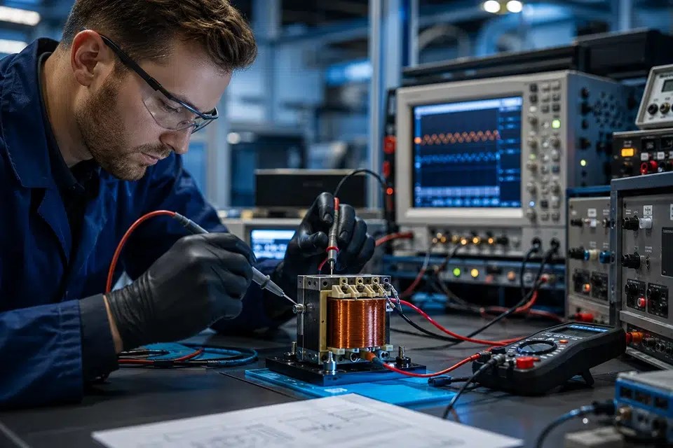
Following reassembly, the transformer undergoes comprehensive testing to verify that it performs according to its design specifications.
Acceptance testing typically includes:
- Turns ratio verification
- Winding resistance
- Insulation resistance
- Applied voltage test
- Induced voltage test
- No-load losses
- Load losses
- Excitation current
- Temperature rise verification (when required)
- Polarity and phase relationship testing
Only after successfully passing all required electrical and mechanical inspections is the transformer approved for return to service.
Transformer Rewinding vs. Transformer Replacement
Selecting between rewinding and replacement depends on the condition of the transformer, operational requirements, lifecycle cost, and equipment availability.
| Feature | Transformer Rewinding | New Transformer |
| Initial cost | Usually significantly lower | Higher capital investment |
| Delivery time | Often weeks | May require several months |
| Existing installation compatibility | Fully maintained | May require installation modifications |
| Custom electrical characteristics | Preserved | May require redesign |
| Core reuse | Yes | No |
| Environmental impact | Lower material consumption | Higher manufacturing footprint |
| Expected service life | Comparable when properly engineered | Full design life |
Rewinding is generally the preferred solution when the magnetic core and structural components remain in good condition. However, transformers with extensive fire damage, severe core deterioration, or major mechanical deformation may be better candidates for complete replacement.
Benefits of Transformer Rewinding
When performed by experienced transformer engineers, rewinding offers numerous technical, operational, and economic advantages.
Restores Original Electrical Performance
Accurately reproduced windings restore the transformer’s voltage ratio, impedance, efficiency, and thermal characteristics to their intended design values.
When supported by comprehensive testing, a professionally rewound transformer can provide performance comparable to a newly manufactured unit.
Extends Service Life
Replacing aged insulation systems and damaged conductors significantly increases transformer reliability.
With proper maintenance, a rewound transformer can often remain in service for decades after refurbishment.
Reduces Equipment Downtime
Many industrial facilities rely on custom transformers that are no longer readily available.
Transformer rewinding often requires considerably less time than designing and manufacturing a completely new transformer, reducing production interruptions and minimizing operational losses.
Lowers Capital Costs
Reusing the magnetic core, enclosure, cooling system, and structural components substantially reduces manufacturing costs.
For medium and large transformers, rewinding frequently represents the most cost-effective lifecycle solution.
Supports Sustainability
Transformer rewinding extends the useful life of valuable electrical equipment while reducing the demand for new raw materials.
Reusing major components lowers waste generation, conserves copper and electrical steel, and reduces the environmental impact associated with manufacturing replacement transformers.
These sustainability benefits align with broader guidance on energy efficiency and resource conservation promoted by the U.S. Department of Energy and international electrical equipment standards.
Common Applications of Transformer Rewinding
Transformer rewinding is widely used across numerous industries where equipment reliability and long service life are essential.
Typical applications include:
- Electrical utility substations
- Industrial manufacturing facilities
- Renewable energy installations
- Mining operations
- Marine and offshore systems
- Rail transportation
- Aerospace ground support equipment
- Medical equipment
- Data centers
- Commercial buildings
It is particularly valuable for specialized transformers whose electrical characteristics or physical dimensions make direct replacement difficult or prohibitively expensive.
Best Practices for Maximizing Transformer Life After Rewinding
A professionally rewound transformer can provide decades of reliable service, provided it is operated within its design limits and maintained according to established engineering practices. While the rewinding process restores the windings and insulation system, long-term reliability depends on proper loading, environmental conditions, and routine condition monitoring.
Implementing a preventive maintenance program helps identify developing issues before they result in insulation degradation or unexpected outages, reducing lifecycle costs and improving system availability.
Operate Within Design Ratings
Operating a transformer beyond its rated voltage, current, or thermal limits accelerates insulation aging and increases the risk of premature winding failure.
To maximize service life:
- Avoid continuous overload conditions.
- Maintain adequate cooling and ventilation.
- Ensure proper voltage regulation.
- Minimize exposure to repeated short-circuit events.
- Monitor operating temperature during periods of high demand.
For custom-engineered transformers, maintaining the original design parameters is especially important because conductor sizing, insulation thickness, and cooling characteristics are optimized for specific operating requirements.
Perform Routine Condition Monitoring
Regular inspections allow maintenance personnel to detect small changes before they become major failures.
Recommended maintenance activities include:
- Visual inspections
- Insulation resistance testing
- Winding resistance measurements
- Transformer turns ratio (TTR) testing
- Oil analysis for liquid-filled transformers
- Infrared thermographic inspections
- Partial discharge monitoring where applicable
Trending these measurements over time provides valuable insight into insulation health and overall transformer condition.
Protect Against Environmental Damage
Environmental conditions significantly influence transformer reliability.
Moisture, airborne contaminants, corrosive chemicals, vibration, and excessive ambient temperatures all accelerate insulation deterioration if left uncontrolled.
Where possible, transformers should be installed in environments that provide:
- Adequate ventilation
- Protection from water ingress
- Minimal dust accumulation
- Stable operating temperatures
- Proper sealing of enclosures
Routine cleaning and inspection of cooling systems also help maintain efficient heat dissipation.
Follow Applicable Industry Standards
Transformer rewinding should always comply with recognized industry standards to ensure safety, reliability, and repeatable performance.
Commonly referenced standards include:
- IEEE transformer testing standards
- IEC transformer standards
- NEMA electrical equipment recommendations
- Applicable customer specifications
- Manufacturer design requirements
Following standardized engineering procedures helps ensure that the rebuilt transformer satisfies both electrical performance and long-term reliability expectations.
Conclusion
Transformer rewinding is a proven engineering solution that restores damaged transformers to safe and reliable operating condition while preserving valuable magnetic and structural components. When performed using precise manufacturing techniques, high-quality insulation systems, and comprehensive electrical testing, rewinding can provide a service life comparable to that of a newly manufactured transformer.
The success of any rewinding project begins with accurate failure analysis and careful evaluation of the transformer’s condition. Engineers must determine whether the magnetic core, insulation structures, and mechanical assembly remain suitable for refurbishment before reconstruction begins. Throughout the process, every stage—from winding removal and reverse engineering to vacuum drying and final acceptance testing—must be completed with strict attention to electrical, mechanical, and thermal design requirements.
For organizations operating industrial facilities, utility networks, renewable energy systems, transportation infrastructure, or other mission-critical electrical equipment, transformer rewinding often provides a cost-effective alternative to replacement. By restoring original performance, reducing equipment downtime, lowering material consumption, and extending asset life, professional rewinding remains an essential part of modern transformer maintenance and lifecycle management.
Frequently Asked Questions
Can a rewound transformer perform like a new transformer?
Yes. When the magnetic core remains in good condition and the rewinding process accurately reproduces the original electrical design, a professionally rewound transformer can deliver performance comparable to a new unit. This requires high-quality materials, precise manufacturing, and comprehensive acceptance testing.
Is transformer rewinding less expensive than purchasing a new transformer?
In many cases, yes. Transformer rewinding typically costs significantly less than replacing a transformer because major components such as the core, tank, structural framework, and cooling system can often be reused. The overall savings depend on the transformer’s size, condition, and application.
How long does transformer rewinding take?
The duration of transformer rewinding varies according to transformer size, design complexity, material availability, and the extent of damage.
Small distribution transformers may be completed within several weeks, while large industrial or utility transformers often require additional engineering, manufacturing, drying, and testing before returning to service.
Can every transformer be rewound?
No. Rewinding is only practical when the magnetic core and structural components remain suitable for continued service.
Transformers with severe fire damage, extensive core deterioration, major mechanical deformation, or catastrophic structural failure are often more economically replaced than repaired.
Does rewinding improve transformer efficiency?
The primary objective of transformer rewinding is to restore the original electrical performance rather than increase efficiency.
However, modern conductor materials, improved insulation systems, and enhanced manufacturing techniques may reduce certain losses and improve long-term reliability when incorporated into an approved engineering redesign.
How is the quality of a rewound transformer verified?
After rewinding, the transformer undergoes comprehensive electrical and mechanical testing.
Typical acceptance tests include:
Turns ratio testing
Winding resistance measurement
Insulation resistance testing
Dielectric withstand testing
Excitation current measurement
No-load and load loss evaluation
Polarity verification
Functional inspection
Only transformers that successfully pass all specified tests should be returned to service.